Building an iSpindel with an ESP32 mini board!
Building an iSpindel using the more modern ESP32 is quite easy, there are a few ESP32 mini boards that work as a drop-in replacement for the ESP8266. These are the options to choose from;
| Board | Description |
|---|---|
| ESP32 s3 mini | Best option (in my opinion) that supports both Wifi and Bluetooth transmission |
| ESP32 s2 mini | The modern replacement for the ESP8266 without Bluetooth support |
| ESP32 c3 mini v1.1 | Good option that supports both Wi-Fi and Bluetooth transmission, but the LED will not work since the pin is also used for the Gyro communication. |
| ESP32 c3 mini v1.0 | Avoid these first versions since it has issues with the antenna (Wi-Fi and Bluetooth). |
| ESP32 c3 pico | New board that has the same features as the c3 mini + a built-in charging chip and voltage divider. |
All of these options are pin compatible with the ESP8266 and will work with available PCB.
Changes compared to ESP8266
When using the ESP32 there are a few differences compared to the ESP8266.
- Diode for wakeup is not needed since that is built into the ESP32 chip.
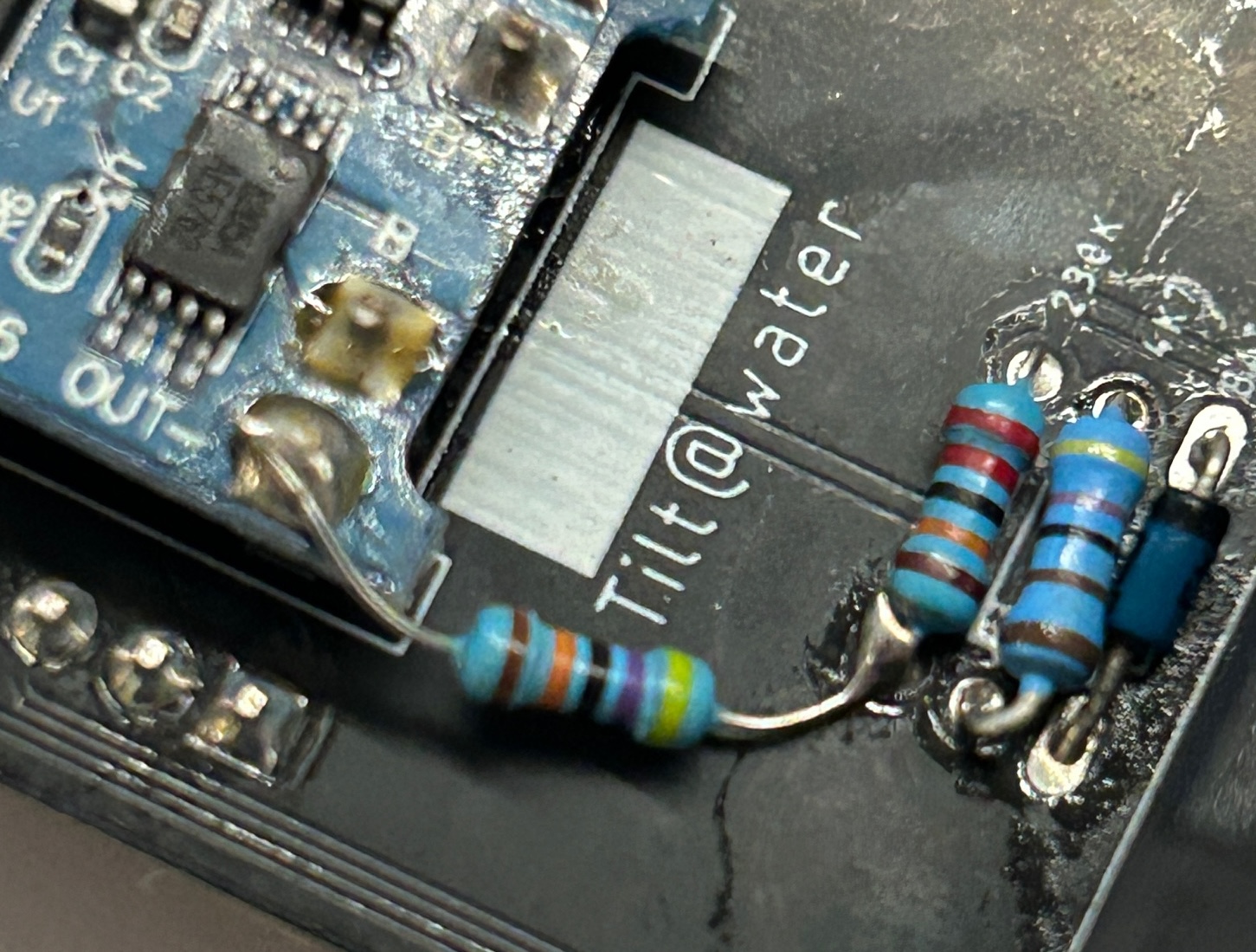
- An ESP8266 has a built in resistor to ground for the analog pin that does not exist on the ESP32. So to get voltage measurements to work we need to add that missing resistor.
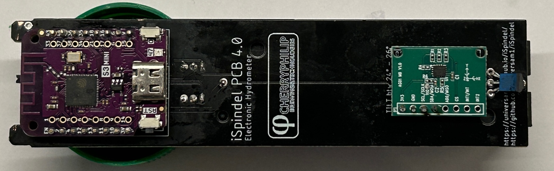
Building your own ESP32 iSpindel
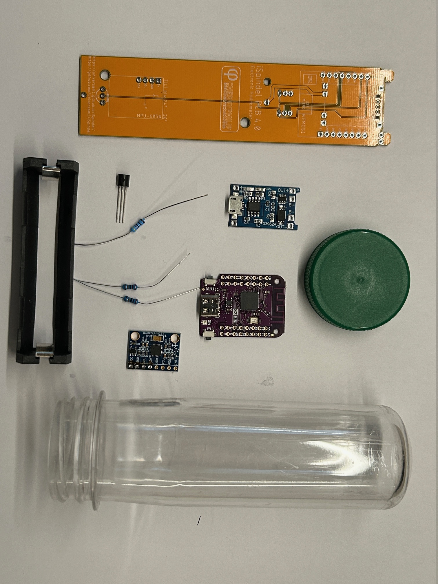
Here I will show how to build a ESP32 based device using the CherryPhilip v4.0 PCB which are the boards I have available. Also consider which gyro you want to use. You will need the following components:
- ESP32 mini board of your choice
- Gyro board of your choice
- Dallas DS18B20 temperature sensor
- 18650 battery + battery holder
- TP4056 battery charging module
- 4.7k resistor for the temperature sensor
- 2 x 220k resistor for the voltage divider
- Off switch that fits your PCB (missing from the picture)
- PCB of your choice
- PET tube
Solder all the components except the diode which is not needed according to the instructions for your PCB. You will only use the outer pins for the ESP32 S3 Mini board.
Add the extra resistor for the voltage divider as shown in this image. It should be between the voltage pin and GND. Here on the CherryPhilip v4.0 PCB I have added that directly to the charging module.
Now you are done with the hardware, next step is to flash the device and configure it. Using my webflasher will make it easy to add the wifi configuration after flashing is completed.
Once you have configured the device then it's time to do the calibration procedure for the gyro and battery measurement. The built-in formula creator in Gravitymon makes this step easy.
Happy brewing, Magnus