Gravitymon PCB
Gravitymon PCB
As part of my shift towards ESP32 I decided to create my own PCB's for Gravitymon so that there is an option that supports all the features and allows me to add more features as we go. I also wanted to have PCB options that support both the PILL case as well as the standard PET used by the original iSpindel. My first focus has been to create a PCB based on the Waveshare ESP32 c3 Zero which is easy to find globally.
I want to send my thanks to andreq/iSpindel-Gravitymon-Pill-PCB who has published a good PCB option for the PILL casing that inspired me to create my own version. I use the PCB outline as well as some of his components as a base for the PILL casing. And yes, I will publish the Kicad files on github once I have had the time to test them properly. I have started a separate repository for all the PCB designs I'm working on since I try to share a lot of components between my designs.
You can find my PCB project here mp-se/pcb-designs.
Schematic for the Gravitymon PCB
This is the latest schematic for Gravitymon where I have added:
- A charging sensor for the wireless charger which will place the device in deep sleep when placed in the charger. This is an improved feature on the deep sleep when placed on the cap which had no good way of waking up the device.
- Soldering points for the wireless charger, any coil that can deliver a 5V output can be used and I have added connections on both edges to make it flexible to mount one. Since charging the device can be used to force it into deep sleep this can act as a simple reset function since that is not exposed on the smaller boards.
- Soldering pads that can be used to help balance the device to as close to 25 degrees as possible. There are two on the bottom and one on the upper side.
- Expose the pins for force configuration mode so that a REED switch (magnetic switch) can be used to force the device into configuration mode without opening the case.
- In v1.2 of the PCB I have converted the logic to 3.3V and not a mix as the original iSpindel design. This latest version will now work with both the Gyros that are supported Updated

- Waveshare ESP32 c3 Zero (18 pin)
- Gyro: MPU-6050 or ICM-42670-P
- LIPO Charger: TP-4056
- Battery holder with surface mount pads
- Battery: 18650, 2200mAh, 44g
- Temperature sensor: DS18B20
- R1: 10k Updated
- R2: 10k Updated
- R3: 3.3k Updated
- R4: 220k
- R5: 220k
- Wireless Charging (XKT510-24) Updated
- On/Off Switch (SK12D07VG3) Updated
- Optional REED switch (normal open) for force config mode Updated
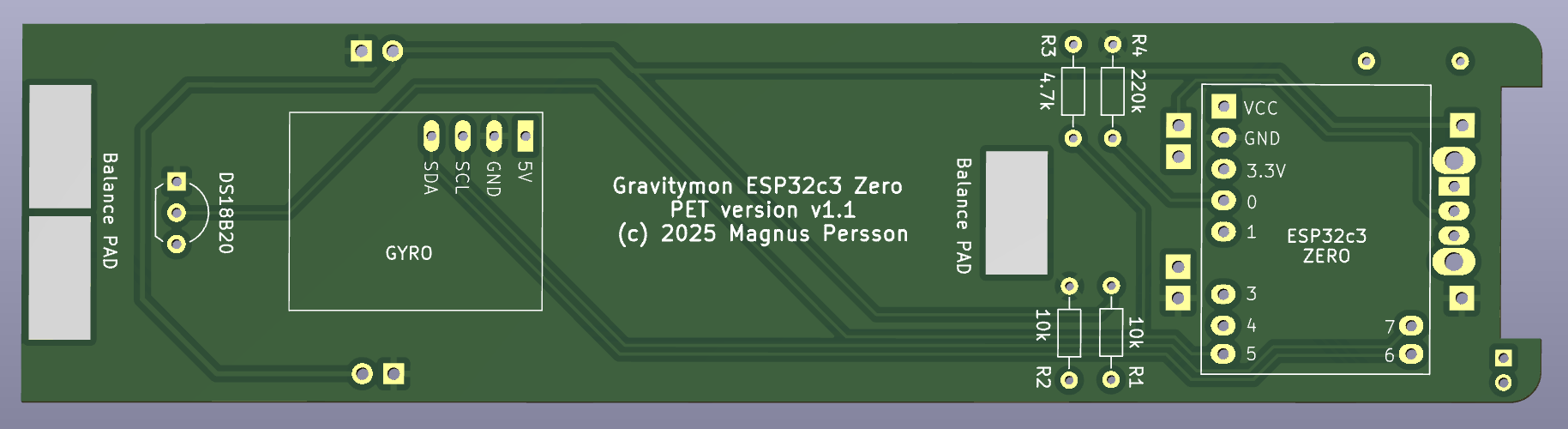
PCB for standard PET
Here is a view of the current PCB for the standard PET casing. This contains the latest changes based on the first prototype. This version I have tested and it fits well into the PET casing and the initial angle was good (around 28 degrees) but with some additional solder pads this should be an easy fix. I estimate it's 1-2g of solder that I need to add.
In v1.1 the values of R1, R2 and R3 have been updated on the silkscreen Updated
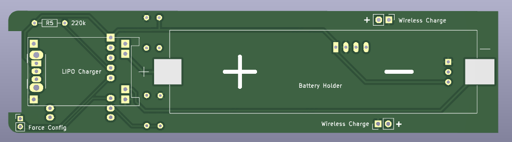
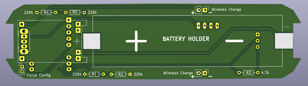
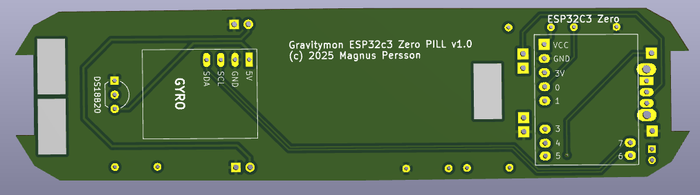
Here is a view of the current PCB for the PILL casing. This contains the latest
changes based on the first prototype. I have made this a little wider than Andre's
project since I found that version was not tight enough. I still have to build a
prototype and test that before ordering the next prototype to make sure I can add
all the components needed and check the balance.
Soon I will order the next set of prototypes and then I will also publish the kicad files on github. If these work fine I will consider creating some PCB options for other CPU's as well. Stay tuned!
Happy brewing, Magnus